
How to Install Ape Hangers: Cables, Wiring and Brakes Wholesale
Most fitment failures come from vertical rise, not bar width.
Installing ape hangers requires more than swapping bars; correct cable routing and verifying brake/throttle line lengths are critical to prevent front-end failure. The primary risk is not aesthetic mismatch but mechanical interference that compromises braking safety and throttle response. Stock cables are engineered for specific geometry limits, and exceeding these without verification leads to immediate operational hazards.
I spent years on the quality control floor before moving to trade. Back in a Riyadh custom shop, a builder fitted our 14-inch ape hangers but ignored cable routing. The brake line stretched too tight across the triple tree, and the throttle cable chafed against the riser clamp. The whole front end had to be torn down. Now, I always tell buyers: measure the rise, then check the brake and wiring lengths. Don’t just swap the bars and hope the cables reach. Route them with slack, or you’ll be rebuilding the cockpit twice. [NEED_CITE: common causes of motorcycle handlebar installation failure]
This guide breaks down the technical steps to ensure safe installation, focusing on the geometry changes that stock components cannot accommodate. Understanding these mechanics helps distributors and builders avoid costly returns and safety liabilities.
Why Do Stock Cables Fail with Ape Hangers?
Vertical rise changes geometry, stretching brake lines beyond safe limits.
The most common misconception is that bar width determines fitment. In reality, vertical rise is the primary driver of cable tension. When handlebars are raised, the distance between the handlebar controls and the master cylinder or throttle body increases significantly. Stock brake lines and throttle cables are cut to precise lengths with minimal excess slack to prevent snagging in the original configuration.
When installing ape hangers, the vertical displacement pulls the cables taut. If the new rise exceeds the available slack, the brake lever may feel stiff, or worse, the line may restrict full handlebar rotation. This restriction can cause unintended braking or throttle application when turning. [NEED_CITE: effects of handlebar rise on brake line tension]
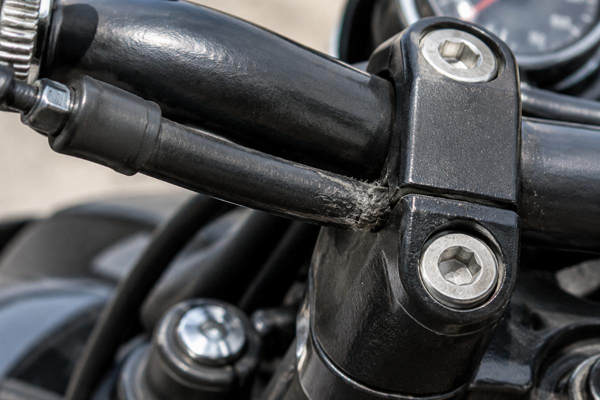
In the Riyadh case, the 14-inch rise created a direct pull on the front brake line. At full lock, the line was under extreme tension, risking rupture at the fittings. The throttle cable, routed internally through the bar, had no room for the necessary bend radius. It rubbed against the metal riser clamp, wearing through the outer sheath and eventually sticking the throttle open. This is not a rare occurrence; it is a predictable outcome of ignoring geometric constraints.
For wholesale buyers, this means that selling ape hangers without corresponding cable kits invites customer complaints. The solution is not to guess but to measure. Stock cables typically accommodate only a few inches of rise. Beyond that, extended lines are mandatory. Failing to verify this leads to a scenario where the bike looks right but functions dangerously.
How to Measure Rise and Check Cable Lengths?
Compare new bar height to stock setup and verify brake line slack at full turn.
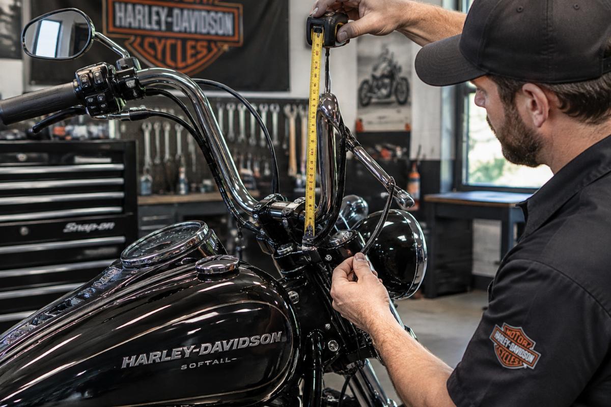
Before ordering parts, accurate measurement prevents the majority of fitment errors. Rise is defined as the vertical distance from the center of the handlebar clamp area to the top of the bar grip area. However, for cable length checks, the relevant metric is the change in distance between the control mounts and the fixed points on the frame or fork.
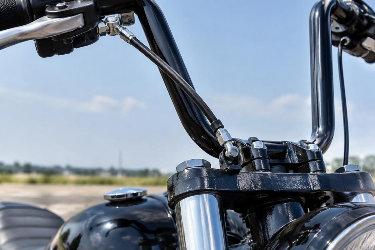
To check cable length, install the new bars loosely without tightening the clamps. Connect the existing cables and route them temporarily. Turn the handlebars fully to the left and then to the right. Observe the brake line and throttle cable. There should be no tension on the lines at full lock. If the lines pull tight or lift the front fork slightly, they are too short. [NEED_CITE: motorcycle handlebar cable length measurement procedure]
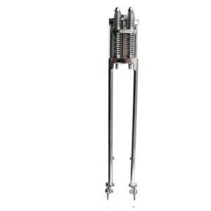
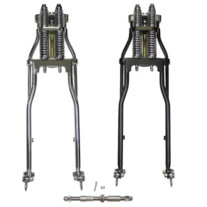
A practical method is to measure the vertical rise of the new bars relative to the stock triple tree height. If the rise exceeds two to three inches, stock cables are likely insufficient. For higher rises, extended brake lines and throttle cables are required. Our springer fork kits and handlebars come with fitment sheets detailing rise dimensions to help buyers pre-check cable compatibility. This proactive step reduces return rates significantly.
Throttle cable chafing is another critical check. Inspect the path where the cable exits the handlebar and enters the riser clamp. Ensure there is enough clearance so the cable does not rub against any metal edges during steering. Internal wiring holes and control clamp area dictate safe bend radius. If the cable bends sharply, it will fail prematurely.
| Fitment Factor | Stock Configuration | High-Rise Ape Hangers | Risk Level |
|---|---|---|---|
| Vertical Rise | Minimal | Significant increase | High if unmeasured |
| Brake Line Slack | Adequate for stock bars | Often insufficient | Critical safety hazard |
| Throttle Cable Path | Smooth curve | Sharp bend potential | Moderate to High |
| Wiring Harness Length | Fits stock routing | May require extension | Low to Moderate |
This table highlights the qualitative shifts in fitment requirements. Distributors should use such comparisons to educate their customers, ensuring they order the correct supporting parts alongside the handlebars.
What Are the Risks of Improper Wire Routing?
Chafing against clamps causes throttle sticking or electrical shorts.
Improper wire routing is a silent killer in custom builds. While brake lines get attention due to visible tension, electrical wiring and throttle cables often suffer from hidden abrasion. When cables are routed tightly, they vibrate against metal surfaces. Over time, this vibration wears through the protective sheathing.
For throttle cables, this wear leads to friction, causing the throttle to stick or return slowly. In extreme cases, the inner cable can fray and snap. For electrical wiring, abrasion exposes the conductors, leading to short circuits. This can cause intermittent electrical failures, blown fuses, or even fire hazards. [NEED_CITE: motorcycle wiring harness failure modes due to abrasion]
In the double rebuild scenario mentioned earlier, the shop swapped bars hoping cables would reach. They did not account for the internal wiring path. The wires were pulled tight against the riser clamp. After a few hundred miles, the insulation wore through, causing a short that disabled the ignition system. The shop had to tear down the cockpit again to replace the wiring harness and reroute it properly.
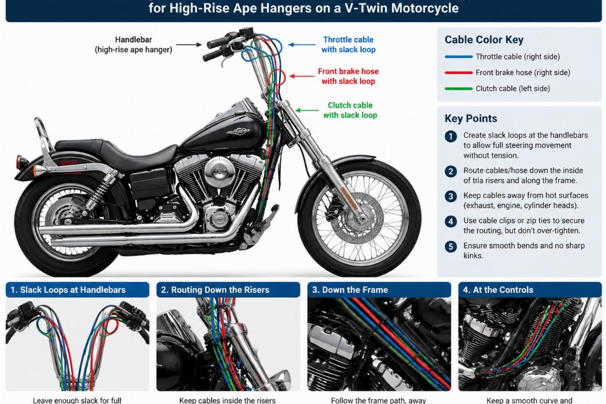
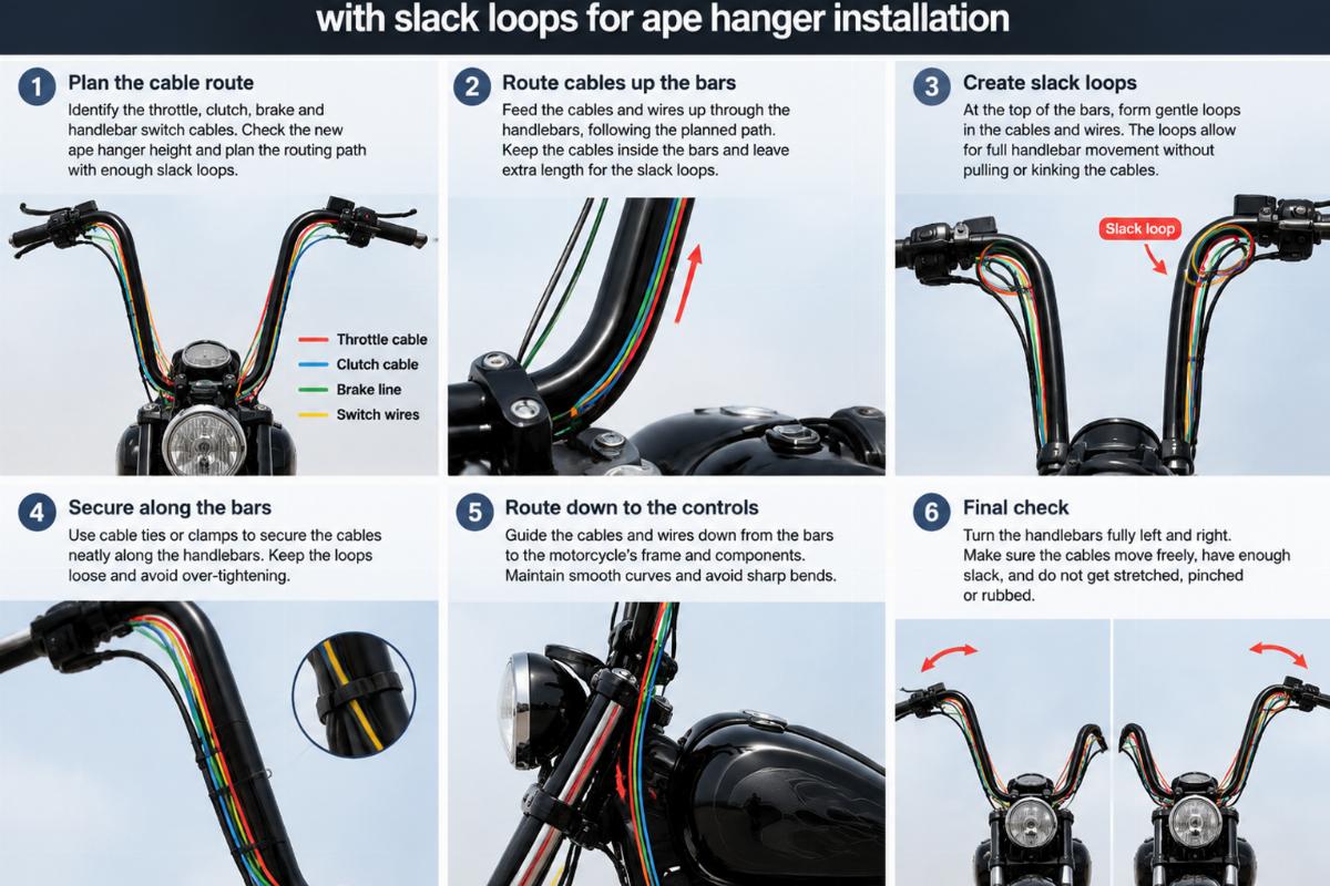
To prevent this, route wiring with intentional slack loops near the steering head. These loops allow the handlebars to turn without pulling on the wires. Secure the wires away from moving parts using zip ties or loom clips. Ensure that the wires do not pinch between the handlebar and the triple tree when the bars are turned.
Another risk is water ingress. If cable ends are not sealed properly, moisture can enter the housing. This leads to internal corrosion, increasing friction and eventual failure. Use dielectric grease on electrical connections and ensure cable ends are capped or sealed.
Step-by-Step Guide to Safe Installation
Route cables with slack loops and secure them away from moving parts.
A systematic approach ensures that all components function correctly after installation. Follow these steps to minimize risk and ensure a professional result.
- Preparation: Remove the old handlebars. Inspect the existing cables and wiring for wear. If any damage is found, replace them before proceeding. Clean the riser clamps and triple tree area.
- Dry Fit: Place the new ape hangers on the risers. Do not tighten the bolts yet. Connect the brake line, throttle cables, and wiring harness. Leave the connections loose to allow for adjustment.
- Check Slack: Turn the handlebars fully left and right. Check for tension on all lines. If any line pulls tight, measure the required extension. Order extended cables if necessary. [NEED_CITE: best practices for motorcycle handlebar cable routing]
- Route Wiring: Create slack loops in the wiring harness near the steering head. Use zip ties to secure the wires to the frame or fork legs, keeping them away from moving parts. Ensure the wires do not rub against the riser clamps or the handlebars themselves.
- Install Cables: Install the extended brake lines and throttle cables if needed. Route them along the same path as the stock lines, but with added slack to accommodate the higher rise. Use cable guides if available to keep lines organized.
- Tighten and Test: Tighten the handlebar clamps to the manufacturer’s specified torque. Bleed the brake system if the brake line was disconnected. Test the throttle for smooth operation and full return. Test the brakes for proper feel and function.
- Final Inspection: Take the motorcycle for a slow test ride. Check for any unusual noises or binding. Re-inspect the cable routing after the ride to ensure nothing has shifted.
This process emphasizes verification at each stage. Rushing through the dry fit or skipping the slack check is the primary cause of post-installation failures. By following these steps, builders can ensure a safe and reliable setup.
For wholesale suppliers, providing clear installation instructions with fitment sheets adds value. It helps dealers avoid technical support queries and ensures end-users have a positive experience. Our documentation includes detailed diagrams for common V-twin models, highlighting critical routing points.
Conclusion
Measure rise, verify slack, and route with care.
Installing ape hangers is a straightforward task when approached with technical precision. The key is to recognize that vertical rise impacts cable and wiring geometry significantly. Stock components are rarely sufficient for high-rise setups. By measuring rise, checking cable lengths, and routing wires with intentional slack, builders can avoid common pitfalls. This approach ensures safety, reliability, and customer satisfaction. For distributors, emphasizing these technical details in product listings reduces returns and builds trust with professional buyers. Always refer to factory service manuals for specific torque values and routing specifications.